Voltage Drop Calculator
Enter the circuit, the wire size and the one-way length to get the voltage drop in volts and percent, with every step.
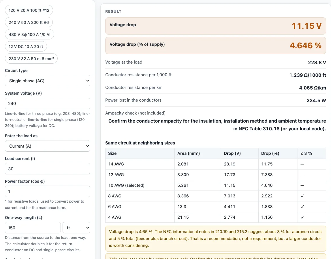
How to use the Voltage drop calculator
- Open the Circuit type drop-down and choose Single phase (AC), Three phase (AC) or DC.
- Enter the System voltage (V). For three phase use the line-to-line voltage (for example 208 or 480). For single phase use 120 or 240. For DC use the battery voltage.
- Open the Enter the load as drop-down and choose Current (A) or Load power (W or kW). If you chose power, enter the Load power and the Power factor (cos φ). Use 1 for resistive loads.
- Enter the One-way length (L) in ft or m, measured from the source to the load.
- Choose a Conductor size system (AWG, kcmil, Metric mm² or Custom area), then pick the size from the matching drop-down.
- Choose the Conductor material (Copper or Aluminum) and the Conductor temperature (20, 60, 75 or 90 °C).
- Read the results: Voltage drop, Voltage drop (% of supply), Voltage at the load and Power lost in the conductors. Check the table of the same circuit at neighboring sizes to compare options.
Under More options you can tick Stranded conductor or enter a reactance value for long AC feeders. The five example buttons above the form load ready-made circuits. Copy link saves every input in the address, Copy result copies the result lines with a link, and Print / save as PDF includes the inputs, results, steps and date. Reset restores the starting example.
What is the formula (equation) for voltage drop?
For DC and single-phase circuits, the voltage drop is VD = 2 × L × I × R. The formula doubles the one-way length because current flows out on one conductor and back on the other. Here L is the one-way length, I is the current and R is the conductor resistance per unit length.
Percent drop is VD ÷ supply voltage × 100. A 240 V circuit carrying 30 A over 150 ft of 10 AWG copper at 75 °C loses about 11.15 V, which is 4.65 % of the supply.
How much voltage drop is acceptable?
The NEC informational notes in 210.19(A) and 215.2(A) suggest keeping the drop to about 3 % on a branch circuit and 5 % total for the feeder plus the branch circuit. These are recommendations, not requirements. Check your local code and the owner’s specification before you treat a value as acceptable.
A 120 V circuit of 20 A over 100 ft of 12 AWG copper at 75 °C loses 7.881 V, or 6.57 %. That is above the branch-circuit suggestion, so a larger conductor would be worth considering.
How do you calculate voltage drop in a three-phase circuit?
For three-phase circuits, use VD = √3 × L × I × R. The √3 factor (about 1.732) replaces the doubling used for single-phase and DC circuits, because three conductors carry the current with a phase relationship between them. L is still the one-way length.
A 480 V three-phase circuit carrying 100 A over 300 ft of 1/0 AWG aluminum at 75 °C loses about 10.43 V, which is 2.17 % of the supply. Enter 480 as the line-to-line voltage.
Does voltage drop change with wire length?
Yes. Voltage drop is proportional to length, because resistance grows with the length of conductor carrying the current. With the same current and conductor, doubling the one-way length roughly doubles the voltage drop.
The same rule applies to resistance: a shorter run gives a smaller drop, and a longer run needs a larger conductor to keep the percentage within the limit you choose.
How do I reduce voltage drop?
Use a larger conductor, because a bigger cross-section has lower resistance per unit length. Shortening the run also helps, since the drop is directly proportional to length. Choosing copper instead of aluminum helps too, because aluminum has about 1.6 times the resistance of copper of the same size.
Reducing the current on a given run also lowers the drop, and for a fixed power a higher system voltage gives a lower current. Compare sizes in the table under the result to see how much each step changes the drop.
Worked examples
| Input | Result |
|---|---|
| Single phase (AC), 240 V, 30 A, 150 ft one way, 10 AWG copper at 75 °C | 11.15 V drop (4.65 %) |
| Single phase (AC), 120 V, 20 A, 100 ft one way, 12 AWG copper at 75 °C | 7.881 V drop (6.57 %) |
| Single phase (AC), 240 V, 50 A, 200 ft one way, 6 AWG copper at 75 °C | 9.801 V drop (4.08 %) |
| Three phase (AC), 480 V, 100 A, 300 ft one way, 1/0 AWG aluminum at 75 °C | 10.43 V drop (2.17 %) |
| Single phase (AC), 230 V, 32 A, 50 m one way, 6 mm² copper at 75 °C | 11.41 V drop (4.96 %) |
Calculated by the tool above with these values.
Frequently asked questions
Is the voltage drop calculator free to use?
Yes. It runs in your browser, is free, needs no sign-up, and does not upload your inputs anywhere. Results can be used in quotes, proposals, reports and service records without attribution.
What is the difference between voltage drop and ampacity?
Voltage drop and ampacity are two separate checks. A wire can pass the voltage-drop limit and still be too small for the current it carries. The calculator does not reproduce ampacity, so confirm it in NEC Table 310.16 or IEC 60364-5-52 for your insulation, installation method and ambient temperature.
What does the stranded conductor option do?
Ticking Stranded conductor under More options adds a 2 % lay allowance to the conductor resistance. This accounts for the extra length of wire in a stranded conductor. Leave it off if you are using solid conductors.
What does the power factor do?
The power factor (cos φ) converts a load power in watts or kilowatts into current. It is also used for the reactance term. Use 1 for resistive loads such as heaters.
Why does the calculator show a warning about reactance?
It appears when you enter a reactance value but the power factor is 1, so the reactive term is zero. Enter the load power factor to include reactance in the result.
Can I save or share my calculation?
Yes. Copy link stores every input in the page address, so the same calculation reopens later. Print / save as PDF gives you the inputs, results, steps and the date.
Does the calculator follow Canadian Electrical Code (CEC) limits?
The calculator’s limit guidance refers to the NEC informational notes, not to CEC rules. If your work follows the Canadian Electrical Code, check the voltage drop and ampacity requirements in your local edition before you rely on the result.
Related tools
- Wire size calculator: use it to find a conductor size for a circuit before you check its voltage drop.
- DC wire size calculator: use it when you are sizing wire for a low-voltage DC system such as a 12 V or 24 V battery circuit.
- Cable size calculator: use it to compare cable sizes when your job is specified in cable rather than wire.
- Watts to amps calculator: use it to convert a load in watts into the current you enter in this calculator.
- Breaker size calculator: use it to choose an overcurrent device once you have the conductor size.
- Ohm’s law calculator: use it to work out voltage, current or resistance from two known values.
- All electrical calculators: use it to browse every electrical calculator on the site.
Sources
- NBS Handbook 100, Copper Wire Tables: copper resistivity 0.017241 Ω·mm²/m, temperature coefficient 0.00393/°C, AWG sizes, stranding allowance
- NBS Handbook 109, Aluminum Wire Tables, Table 1: EC aluminium 0.028264 Ω·mm²/m, 0.00403/°C
- IEC 60228 conductor sizes and resistances (summary)
- NFPA 70, National Electrical Code (free online access): sections cited on this page; no tables are reproduced