Fault Current Calculator
Enter the transformer and the feeder to get the available fault current at both ends, in kA.
The fault current calculator estimates how much current can flow during a short circuit at a transformer’s secondary terminals and at the far end of a feeder. It also serves as an available fault current calculator, a transformer fault current calculator, or a short circuit calculator, since people search for the same planning result under each of those names.
The tool runs in your browser, is free, and needs no sign-up. Nothing you enter is uploaded. Enter the transformer kVA, secondary voltage, phase, and nameplate %Z to get the fault current at the transformer terminals. Add a feeder conductor size, material, parallel sets, and length to see how much the cable reduces the current at the far end.
How to use the Fault Current Calculator
- Enter the Transformer rating (kVA) and the Secondary voltage (V, line-to-line). To try a set of numbers, click one of the example buttons above the form.
- Choose Phase: Three phase or Single phase.
- Enter the Transformer impedance (%Z) from the transformer nameplate.
- For a feeder, enter the Feeder conductor size in AWG, kcmil, or mm². Then choose the Conductor material and the number of Conductors per phase (parallel sets).
- Enter the Feeder length (one way) in ft or m. Enter 0 to calculate the transformer terminals only.
- Under More options, enter the Reactance (Ω per 1,000 ft) from your cable maker’s data, or leave it blank to count resistance only, which gives the higher, conservative result. The Utility short-circuit capacity (MVA) is optional. Leave it blank for an infinite bus.
- Read the result rows. Only the rows that apply to your chosen mode appear. Then check any warnings and open How it was calculated to see each step with your numbers.
When the result is ready, Copy result copies the result lines with a link. Copy link stores every input in the page address, so you can reopen the same calculation later. Print / save as PDF produces a copy with the inputs, results, steps, and date. Reset restores the starting example.
How do you calculate transformer fault current?
Start with the transformer’s full-load current. For a three-phase transformer, I_FLA = kVA × 1,000 ÷ (√3 × V). For a single-phase transformer, I_FLA = kVA × 1,000 ÷ V. The voltage is the secondary line-to-line voltage.
Next, divide that current by the per-unit impedance. The formula is I_SC = I_FLA × 100 ÷ %Z, where %Z is the nameplate impedance. This gives the fault current at the secondary terminals when the utility source is treated as infinite, meaning it adds no impedance of its own.
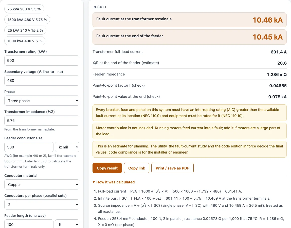
For example, take a 500 kVA, 480 V, three-phase transformer with 5.75 %Z. I_FLA = 500 × 1,000 ÷ (1.732 × 480) = 601.4 A. Then I_SC = 601.4 × 100 ÷ 5.75 ≈ 10,460 A, or about 10.46 kA.
A single-phase result is the line-to-line fault at the secondary. A line-to-neutral fault on a center-tapped secondary can be higher at the terminals, and the calculator does not compute it.
How do you calculate available fault current?
Available fault current at a point is the fault current that point can receive from the source. Where a feeder runs between the transformer and a load, the cable adds impedance, so the fault current at the far end is lower than at the transformer.
The calculator works out the conductor resistance from the conductor’s resistivity at 75 °C, the number of parallel sets, and the length. If you enter the cable’s reactance per 1,000 ft from the maker’s data, it adds that too; left blank, the feeder counts as resistance only, which overstates the fault current slightly and so errs on the safe side for equipment ratings. Combining resistance and reactance gives the feeder impedance, which then reduces the fault current.
With the default setting of two sets of 500 kcmil copper at 100 ft and no reactance entered, the fault current at the end of the feeder is 10.45 kA, barely below the 10.46 kA at the terminals: a short, heavy feeder adds little impedance. Longer or smaller feeders reduce it much more; the 75 kVA, 208 V example drops from 5.948 kA to 5.882 kA.
An infinite-bus result is the highest value the source can produce, so it is a conservative figure for equipment ratings.
Worked examples
| Input | Result |
|---|---|
| 500 kVA, 480 V, 3φ, 5.75 % impedance | 10.46 kA at the transformer, 10.45 kA at the end of the feeder |
| 75 kVA, 208 V, 3φ, 3.5 % impedance | 5.948 kA at the transformer, 5.882 kA at the end of the feeder |
| 1500 kVA, 480 V, 3φ, 5.75 % impedance | 31.38 kA at the transformer, 31.36 kA at the end of the feeder |
| 25 kVA, 240 V, 1φ, 2 % impedance | 5.208 kA at the transformer, 5.137 kA at the end of the feeder |
| 1000 kVA, 400 V, 3φ, 6 % impedance | 24.06 kA at the transformer, 24.03 kA at the end of the feeder |
Calculated by the tool above with these values.
Frequently asked questions
What is the point-to-point method?
The point-to-point method is a shortcut for finding the fault current at one point when you already know it at an earlier point. It uses a multiplier, called the f factor, that depends on the impedance between the two points. The calculator shows the f factor and the point-to-point value at the end of the feeder as a check on its main result.
Why does available fault current matter?
Every breaker, fuse, and panel must have an interrupting rating at least equal to the available fault current at its location (NEC 110.9), and the equipment must be rated for that current (NEC 110.10). If the rating is too low, the device may fail to interrupt a fault safely. Knowing the value at each point lets you check that the equipment is suitable.
What does the X/R ratio at the end of the feeder show?
The X/R row is an estimate of the ratio of reactance to resistance in the feeder impedance. It is a planning value and does not change the fault current figures. It can be useful when you need more detail for equipment or breaker testing.
What happens if I enter a feeder length of 0?
The calculator treats the transformer terminals as the only point of interest. Only the transformer terminal result appears, and no feeder rows are shown.
Does the result include motor contribution?
No. Running motors feed current into a fault, and that contribution is not included. If motors make up a large part of the load, add the motor contribution to the result using a separate study.
Can I use this for a single-phase transformer?
Yes. Choose Single phase, and the calculator uses I_FLA = kVA × 1,000 ÷ V. The result is the line-to-line fault at the secondary. The calculator warns that a line-to-neutral fault on a center-tapped secondary can be higher at the terminals, and it does not calculate that case.
Related tools
- Transformer sizing calculator: use it to choose a transformer kVA rating before you check its fault current.
- kVA calculator: use it to convert between kW, kVA, and current for a load.
- Breaker size calculator: use it to pick a breaker size for a circuit once you know the fault current at its location.
- Voltage drop calculator: use it to check the voltage loss along the same feeder.
- Three phase power calculator: use it to find power and current for a three-phase circuit.
- All electrical calculators: use it to browse every calculator on the site.
Sources
- CSE Magazine, Approximating short-circuit calculations for conductors: point-to-point method
- NBS Handbook 100, Copper Wire Tables: copper resistivity 0.017241 Ω·mm²/m, temperature coefficient 0.00393/°C, AWG sizes, stranding allowance
- NBS Handbook 109, Aluminum Wire Tables, Table 1: EC aluminium 0.028264 Ω·mm²/m, 0.00403/°C
- NFPA 70, National Electrical Code (free online access): sections cited on this page; no tables are reproduced